
Personal project · Completed exploration
Two-stage cycloidal gearbox
Exploring an alternative cycloidal reduction mechanism.
- Overall reduction
- 84:1 measured overall ratio
- Prototype work
- 12 printed iterations
- Validation
- Motion demonstrated; output torque not measured
The project
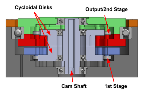
I investigated a different way to use a cycloidal gearbox: remove the inner lobes used in the traditional design, pin two cycloidal disks together in a two-stage arrangement, and use their eccentric motion to obtain reduction. The prototype achieved a measured overall reduction of 84:1 across twelve printed iterations. Torque-output testing remained incomplete.
The mechanism I wanted to explore
The central question was whether a different disk-and-pin arrangement could turn eccentric motion into useful output reduction without the traditional inner lobes. I moved from an early conventional cycloidal prototype to two pinned disks arranged across two stages, exploring how their coupled motion could drive the output.
This was an experimental mechanism study for a robotic drivetrain. The measured 84:1 ratio describes the prototype’s input-to-output rotation relationship; it does not establish its efficiency or torque capacity.
From CAD to the bench
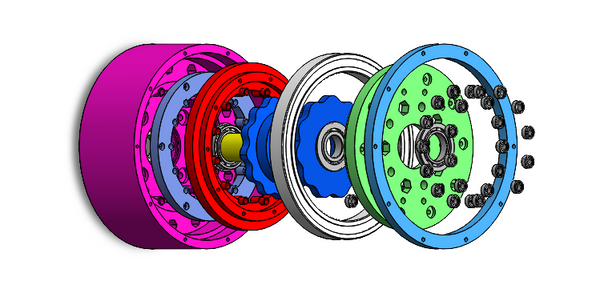
I modeled the disks, pin carriers, bearing seats, motor mount, and output assembly in SolidWorks, then fabricated PLA parts with FDM printing. The test setup used a NEMA-17 stepper, Arduino, and A4988 driver.
What the prototype taught me
Early parts bound in the output stage. Changing printers required another tolerance adjustment. Added clearance finally produced motion, but also intermittent engagement and roughly 9° of measured backlash in that iteration.
I progressively added tape to the disks to reduce clearance, working back from the binding point to investigate its effect on engagement. That experiment made the tradeoff between free motion and lost motion tangible.
Project status
Work on this prototype ended before torque-output and further performance testing could be completed. The project demonstrated assembly and motion, but its torque capability was not validated.
I’m now applying those lessons to a two-stage planetary gearbox for the base of a desktop robot arm.
Engineering lessons
Clearance is a tradeoff between binding and lost motion.
Increasing clearance made the prototype move, but also introduced intermittent engagement and about 9° of backlash in that iteration. Smooth motion and repeatable positioning require more than simply making the parts fit.
Tolerances belong to a manufacturing process.
Switching printers required another fit adjustment. Clearances that work on one printer should not be assumed to transfer unchanged to a different fabrication setup.
Use reversible changes to isolate a cause.
Adding tape to the disks changed the clearance without requiring another full print. Working toward binding and then backing off helped investigate how contact and engagement contributed to the motion problem.
Separate gear ratio from mechanical efficiency.
The 84:1 reduction describes the relationship between input and output rotations. Friction and binding can reduce the torque delivered, but a difference in counted rotations alone does not measure efficiency. That requires torque and speed measurements under load.
Validate motion, backlash, and torque independently.
A moving assembly is an important milestone, but it does not establish load capacity or positioning accuracy. Torque-output testing remained incomplete, so the prototype’s motion should not be treated as a validated torque result.
Diagnose the symptom before choosing the fix.
The prototype showed binding, intermittent engagement, and about 9° of backlash. These are different symptoms: extra clearance can relieve binding while worsening lost motion. A future test should record each symptom independently rather than using free rotation as the only pass condition.
Record the configuration behind each result.
A change of printer required another tolerance adjustment, and tape changed disk clearance without a full reprint. Recording the printer, part revision, and clearance changes alongside each observation would make the experiment easier to repeat and the next geometry change easier to justify.