
Personal project · In progress · Started approximately September 2026
5-DOF desktop robotic arm
In progress: Joint 1 built, with the full arm still in development.
- My work
- Joint design, printed gearbox, motor control
- Built
- Joint 1 · 15.16:1 reduction
- Next
- Resolve Joint 2 packaging and torque requirements
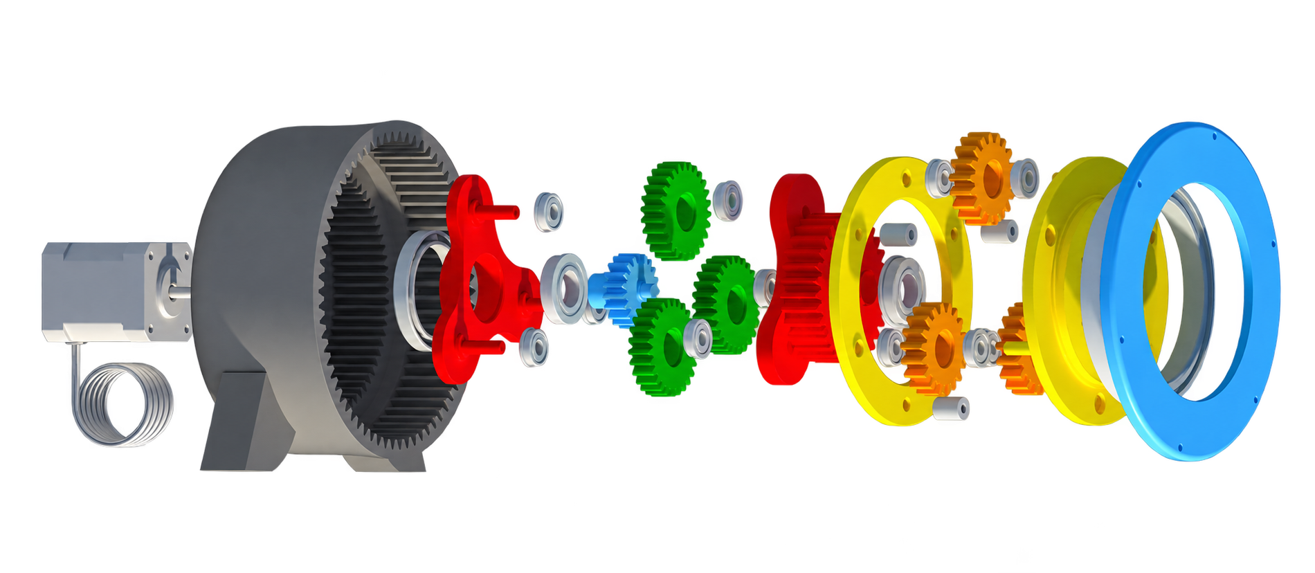
From gearbox to robotic joint
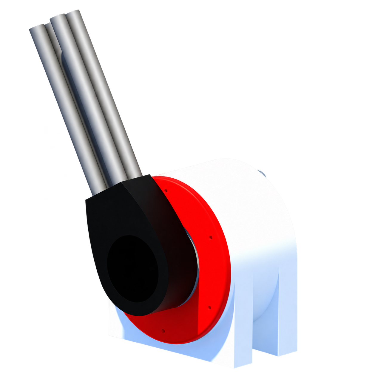
What began as a compact planetary gearbox has grown into a full five-degree-of-freedom robotic arm. I’m developing the mechanical joints, stepper-driven transmissions, and a custom control board as one integrated system.

- 5 DOF
- Target arm architecture
- 15.16:1
- Built Joint 1 reduction
- 16:1
- Planned Joint 2 reduction
Joint 1: built
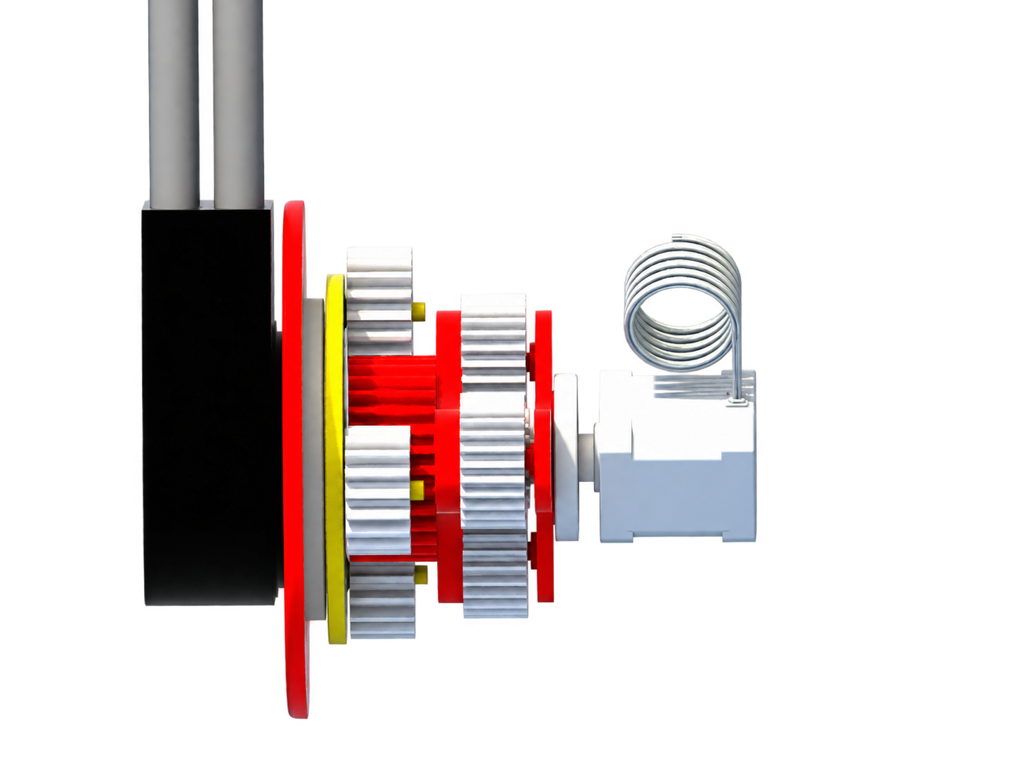
The base joint uses two fixed-ring planetary stages in one PETG housing. A 4.737:1 first stage and 3.2:1 second stage produce the 15.16:1 overall reduction. The arm link bolts directly to the output flange, while an 80 × 100 mm thin-section bearing carries the link’s bending load.
Joint 2: designed, not yet built
The current concept uses two 4:1 stages with 12-tooth suns, 12-tooth planets, and one shared 36-tooth ring. Before CAD is finalized, I need to confirm the bracket bore, choose a compact planet-bearing approach, and define the joint torque requirement.
Controls in development
I’m designing my first custom PCB in KiCad around an ESP32 and four stepper drivers. The controls work builds on an Arduino and A4988 breadboard prototype used to test the NEMA 17 motor and motion profiles.
Measure the Joint 2 bracket bore and select its planet bearing. Those two decisions determine whether the compact 12/12/36 gearset is practical.
Engineering lessons
Design the load path, not just the gear ratio.
The arm link creates a bending moment as well as a demand for drive torque. The output flange and thin-section bearing give that load a support path; increasing the reduction ratio alone would not solve the structural problem.
Resolve bearing and packaging constraints early.
The compact Joint 2 gearset still depends on the bracket bore and planet-bearing arrangement. Those interfaces need to be resolved together before the gear geometry is finalized.
Choose the transmission around the joint requirements.
A higher reduction trades output speed for torque multiplication, but useful torque still depends on the motor and mechanical losses. Defining the joint’s load and motion requirements is the next step before committing to its transmission.
Prototype the interfaces before the full assembly.
Joint 1 is built while Joint 2 remains a packaging study. That sequence makes the motor, bearings, housing, and link interfaces tangible before the full arm is committed. For the next joint, a small bearing-and-bracket prototype would answer fit questions earlier than a complete print.
Keep planned performance separate from demonstrated hardware.
The 15.16:1 base transmission is built; the 16:1 second joint and five-axis system are still targets. Tracking those states separately keeps the next decisions focused on the unverified interfaces, loads, and controls rather than treating a complete CAD model as a complete robot.